1200 getting modded to accept a left rear cam drive for the C5 ignition.

Classic Goldwings

Help Support Classic Goldwings:

This site may earn a commission from merchant affiliate links, including eBay, Amazon, and others.

dan filipi

Well-known member
Staff member
Administrator
Moderator
Supporting Member
Joined
Dec 3, 2009
Messages
22,403
Reaction score
238
Location
Van Nuys Ca.
My Bike Models
1983 Interstate
2018 KLR 650
2018 BMW S1000 RR
My Bike Logs forum link
https://classicgoldwings.com/forums/dan-filipi.122/
This 1200 F.I model right cam housing could work on the left or right head but the housing not being deep enough for the electronic module presented other problems....

image.php


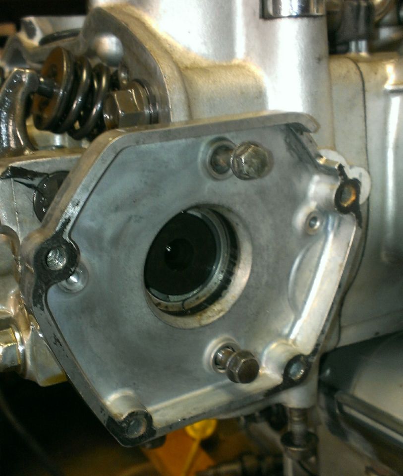
So I went forward with plans to modify the sexy C5 GL1000 housing.....

image.php


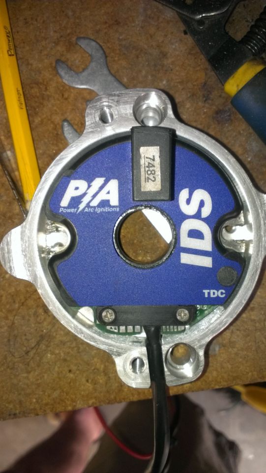
With the C5 module re-fitted to the GL1000 housing..time to make a drive off the left head..

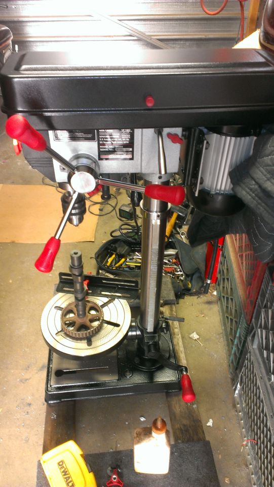
Cam center drilled and tapped to M8..

image.php


Back on the bike..

[video]https://www.youtube.com/watch?v=EUMrJAAFlrE&feature=youtu.be[/video]

Next is fit the C5 housing to the head.

To be continued..
 
I like where you are heading Dan :good:
$500 ignition on a $40 engine :smilie_happy:
 
Dan once you get it running, I'll help you make a stainless steel shaft like we make for Viragos, Kawasaki W1, and GL1500. It will run true and the height can be set perfect so there is no adjustment needed by the installer. Great work!!

I am so excited you've been working on this project. It is very promising and the back of the head is really ideal for a mounting location for several reasons.
Happy Fathers Day!!

-Paul Crowe
C5 Performance
 
[url=https://www.classicgoldwings.com/forum/viewtopic.php?p=121234#p121234:ztkmthns said:
C5Performance » Sat Jun 14, 2014 8:26 pm[/url]":ztkmthns]
Dan once you get it running, I'll help you make a stainless steel shaft like we make for Viragos, Kawasaki W1, and GL1500. It will run true and the height can be set perfect so there is no adjustment needed by the installer. Great work!!

I am so excited you've been working on this project. It is very promising and the back of the head is really ideal for a mounting location for several reasons.
Happy Fathers Day!!

-Paul Crowe
C5 Performance
Pics Paul?
I'm not married to any one method here so looking for ideas.
 
Moving forward.

The C5 housing wasn't going to fit since the head screw holes line up just right in the WRONG place...

image.php


Just about centered with the front in the housing sides..
image.php


So made an adaptor. Not pretty but it works well..

image.php


image.php


image.php


I'm not crazy how it looks but it's solid and straight.

image.php
 
Thanks Joe.

Next up is setting the encoder depth.
Just about got that done so it runs true.

Boy, gotta appreciate what Paul has gone through making these kits virtually plug and play.
This has been a challenge for me so far.
I'm not sure my final deal here will be a threaded stud. At first it seems logical and easiest way to set the encoder wheel depth but there are issues locking the wheel in place.
 
Are you thinking of using two nuts to lock it in place? With one nut set deep enough, you could loc-tite it in place (or use a lock nut) and still use the aluminum bushing and then lock everything in place like the 1100 stock system...
 
[url=https://www.classicgoldwings.com/forum/viewtopic.php?p=121338#p121338:1qilygxx said:
brianinpa » Mon Jun 16, 2014 7:05 am[/url]":1qilygxx]
Are you thinking of using two nuts to lock it in place? With one nut set deep enough, you could loc-tite it in place (or use a lock nut) and still use the aluminum bushing and then lock everything in place like the 1100 stock system...
Well setting the depth is fairly easy.
Problem I'm running into is lack of a sleeve the proper diameter to go over the 8mm bolt so it spins true. The wheel then has to be locked in place while it sits on the OD of the sleeve.
 
[url=https://www.classicgoldwings.com/forum/viewtopic.php?p=121343#p121343:1bzarut8 said:
brianinpa » Mon Jun 16, 2014 7:14 am[/url]":1bzarut8]
It can never be easy...
Oh to have a lathe...... :fiddle:
 
How 'bout using your new drill press as a lathe - put an 8mm stud in the chuck, lock a couple of nuts onto it, and as it spins, file a portion of a nut smooth until you get the diameter you need for the encoder to fit over it.

:headscratch: :laptop:
 
That's pretty much where I'm heading with this.
I need a bolt with an 11mm smooth section that I can center tap for a 6 mm bolt and end tap to 8mm.
I could also tap the cam to a bigger bolt.
It's hard finding good hardware outlets for stuff like that here in the valley. Many of the good places have closed.
 
[url=https://www.classicgoldwings.com/forum/viewtopic.php?p=121341#p121341:28syjwl0 said:
dan filipi » Mon Jun 16, 2014 9:11 am[/url]":28syjwl0]
[url=https://www.classicgoldwings.com/forum/viewtopic.php?p=121338#p121338:28syjwl0 said:
brianinpa » Mon Jun 16, 2014 7:05 am[/url]":28syjwl0]
Are you thinking of using two nuts to lock it in place? With one nut set deep enough, you could loc-tite it in place (or use a lock nut) and still use the aluminum bushing and then lock everything in place like the 1100 stock system...
Well setting the depth is fairly easy.
Problem I'm running into is lack of a sleeve the proper diameter to go over the 8mm bolt so it spins true. The wheel then has to be locked in place while it sits on the OD of the sleeve.

Dan, here is the Virago stainless shaft, with hex nut built in. This threads into the cam, and we mount the encoder wheel using a "top and bottom" aluminum cup. It's a mix of Moto Guzzi and Kawasaki projects all rolled into one. This would probably be the best way to have a "true" running shaft at the correct height.
 

Attachments

  • 100_2259.JPG
    100_2259.JPG
    87.7 KB · Views: 105
  • 102.JPG
    102.JPG
    47.6 KB · Views: 105
  • assembled without cap.jpg
    assembled without cap.jpg
    24.1 KB · Views: 110

Latest posts

Top