Rebuild '82 Standard Wire Harness and Fuse Box

Classic Goldwings

Help Support Classic Goldwings:

This site may earn a commission from merchant affiliate links, including eBay, Amazon, and others.
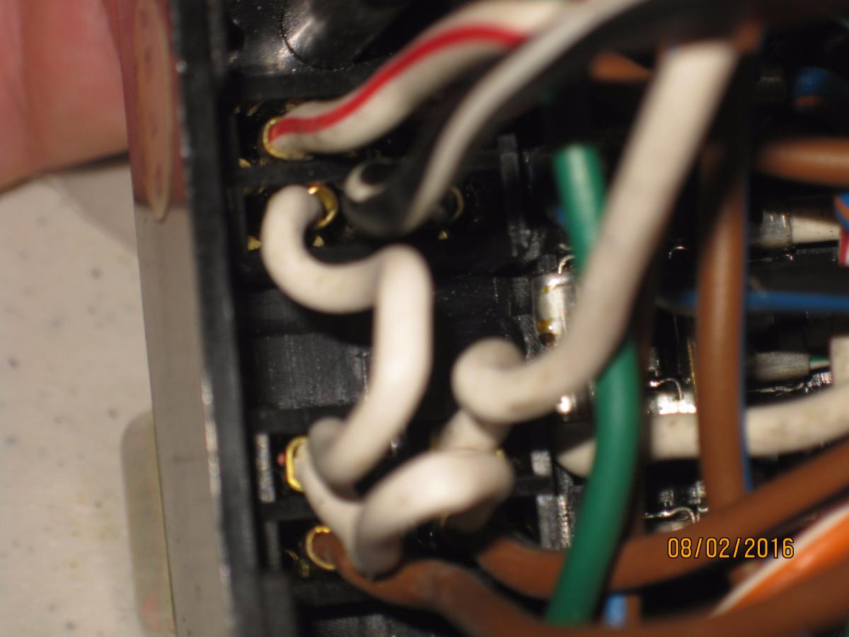
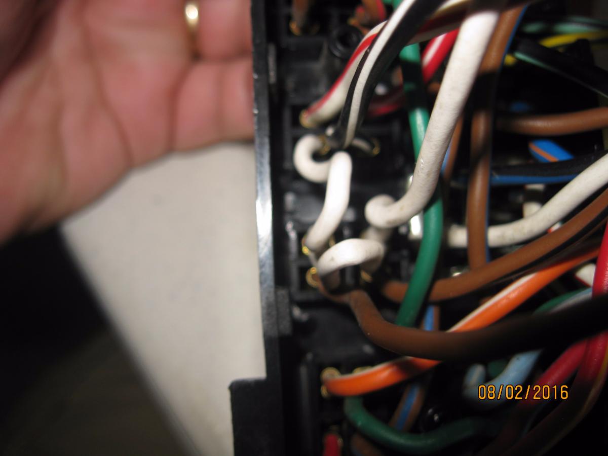
However, in these pics of the CFI and Fuel pump relays, I cannot find which wire is ground:

image.php


image.php


Here is a schematic of these two relays:

Relays.JPG


You can see that the bottom left spade (white wire) of the CFI relay comes off the spade and connects to the top left spade on the fuel pump relay and is jumped across to the top right spade of the fuel pump relay where it then leaves and goes out to the harness.
 
[url=https://classicgoldwings.com/forum/viewtopic.php?p=177913#p177913:3t0ebbzn said:
Donpauli2 » Sat Jul 30, 2016 6:47 pm[/url]":3t0ebbzn]
Have you actually checked the gauge sizes with a wire cutter to check conductor size.

It is a good idea to be sure. My measurements are based on wire I have in the shop and the paper gauge I have used in the past. So, I went and bought a REAL stainless steel wire gauge tool. All of the wires on the 86 SEI fuse box measure 14 gauge:

image.php


image.php


Remember that Green/Black from the '82 fuse box to the Acc terminals? Well, at best it measures 20 gauge! I checked a few more of the fuse box wires on the '82 and they are all measuring 20 gauge. :shock:

image.php


The ground wire in the '82 harness measures 14 gauge:

image.php


And the black hot wire from the key switch to the fuse box on the '82 harness also measures 14 gauge.

image.php
 
Gerry, I could type it out but it would be easier if you went to page 192 of the 1200 electrical troubleshooting manual and it shows where each of the wires goes for the CFI relay and the Fuel pump relay. That way you will have a ready reference available
 
[url=https://classicgoldwings.com/forum/viewtopic.php?p=178159#p178159:1x0pvhtg said:
backlander » Tue Aug 02, 2016 4:51 pm[/url]":1x0pvhtg]
Gerry, I could type it out but it would be easier if you went to page 192 of the 1200 electrical troubleshooting manual and it shows where each of the wires goes for the CFI relay and the Fuel pump relay. That way you will have a ready reference available
Thanks! I guess I am still having trouble looking at just 1 relay and assuming which spade is always ground. It might be easier if I take all of these pics from the manual for the electrical and put them into a PDF.

image.php
 
[url=https://classicgoldwings.com/forum/viewtopic.php?p=178167#p178167:2ewgr2cf said:
dan filipi » Tue Aug 02, 2016 7:35 pm[/url]":2ewgr2cf]
I should have that manual in PDF if you want it. I could put it somewhere for you to download.
That would be great Dan! Can't PDF's be posted in a thread for attachments?
 
I would love to download the complete Honda 1200 manual if that is possible Dan :thanks:
 
[url=https://classicgoldwings.com/forum/viewtopic.php?p=178159#p178159:bwwg562y said:
backlander » Wed Aug 03, 2016 7:51 am[/url]":bwwg562y]
Gerry, I could type it out but it would be easier if you went to page 192 of the 1200 electrical troubleshooting manual and it shows where each of the wires goes for the CFI relay and the Fuel pump relay. That way you will have a ready reference available
Thanks Mike I was pretty sure that was going to be how the relays were wired up ( as per many vehicles ECU and pump relays) but I didn't want to give Gerry a bum steer until I had worked it out.
 
[url=https://classicgoldwings.com/forum/viewtopic.php?p=178203#p178203:s63tqu2s said:
julimike54 » Wed Aug 03, 2016 7:42 am[/url]":s63tqu2s]
Glad you passed the test and they let you go play :)
Thanks, but I am not out of the woods yet. I am doing more testing today and had an MRI last night. I have been cheating a bit by looking up information and taking pictures of the bike. :hihihi:

I do have a diagnosis now (Bradycardia), they are now trying to find out why.
 
Top right is the trigger positive and bottom right is the trigger negative, when switch triggers relay power from fuse turns light on.

Sometimes you will find relay with five pins, in those cases you have a normally closed side of the relay, meaning it is a complete circuit until the relay is triggered then it goes open and closed on the other side. Hope this makes sense, there are also six pin relays and they will activate two separate circuits.
 
As long as the relay coil is not diode protected it doesn't matter which side of the coil is positive or negative.
 
As I work through doctor visits and testing, I am also working through the 86 schematics. As I follow each circuit I see why the heavier wire was used. Some of the complaints we have had in the past about adding a relay for the coils or a relay for the horn circuit or even adding a buss bar for either a positive buss or negative buss are addressed in this fuse panel.

Honda kinda took care of all of that in this fuse panel. There is a 12 gauge wire coming from the 30 amp fuse to the key switch and there is also another positive wire going to another 30 amp fuse which is always hot. This circuit runs to the lower 3 fuses as an "unswitched" circuit (always hot). The key switch sends each of the sections (On/ACC/Park) back to the fuse panel with individual 14 gauge wires with those wires being bussed on several different circuits in the fuse panel. Big amperage units get their power from the relays.

It is going to be cool installing this fuse panel with the relays. It will require a careful review of my current '82 harness and most definitely adding larger wires in my harness to match up some of these circuits. I am under the opinion that in the end it will be a great improvement to the bikes circuits!
 

Latest posts

Top