hmm thats cool
You are using an out of date browser. It may not display this or other websites correctly.
You should upgrade or use an alternative browser.
You should upgrade or use an alternative browser.
1200 getting modded to accept a left rear cam drive for the C5 ignition.
- Thread starter dan filipi
- Start date


Help Support Classic Goldwings:
This site may earn a commission from merchant affiliate
links, including eBay, Amazon, and others.
Gotta love nice machine work!
OP
OP
- Joined
- Dec 3, 2009
- Messages
- 22,403
- Reaction score
- 238
- Location
- Van Nuys Ca.
- My Bike Models
- 1983 Interstate
2018 KLR 650
2018 BMW S1000 RR
- My Bike Logs forum link
- https://classicgoldwings.com/forums/dan-filipi.122/
That is nice stud there Paul.
I have an idea.
Will update if it works.
I have an idea.
Will update if it works.
OP
OP
- Joined
- Dec 3, 2009
- Messages
- 22,403
- Reaction score
- 238
- Location
- Van Nuys Ca.
- My Bike Models
- 1983 Interstate
2018 KLR 650
2018 BMW S1000 RR
- My Bike Logs forum link
- https://classicgoldwings.com/forums/dan-filipi.122/
My last post was about something else but thought I'd post a vid where I'm at right now.
[video]https://youtu.be/itMi5PvD300[/video]
This may be as far as I go and run with it, unless Paul wants to make me up one a dem fancy dancy stainless steel studs.
[video]https://youtu.be/itMi5PvD300[/video]
This may be as far as I go and run with it, unless Paul wants to make me up one a dem fancy dancy stainless steel studs.
that looks as good as any machine shop can do in the important part it looks true spinning
The cloaking device for the electronics is working great! And you really know how to hide wires! :hihihi:
Seriously, it looks good! It appears to be spinning straight and true...is the depth correct here?
Seriously, it looks good! It appears to be spinning straight and true...is the depth correct here?
OP
OP
- Joined
- Dec 3, 2009
- Messages
- 22,403
- Reaction score
- 238
- Location
- Van Nuys Ca.
- My Bike Models
- 1983 Interstate
2018 KLR 650
2018 BMW S1000 RR
- My Bike Logs forum link
- https://classicgoldwings.com/forums/dan-filipi.122/
Yes the depth is set there where I need it.
I will put the module in and maybe get it hooked up.
I will put the module in and maybe get it hooked up.
History will be made again!
- Joined
- Jan 27, 2013
- Messages
- 9,855
- Reaction score
- 34
- Location
- Brisbane Australia
- My Bike Models
- 1981 GL1100 “Rats Nest”
1998 GL1500c Val
1987 CBR1000f “The Pig”
1991 CBR1000f Red
Before you know it you will be a multi- sparky (as per the side of your van) :smilie_happy:
Dan (or anyone else wanting a shaft as I've shown), we need to know the height from the base of the cam to the encoder.
Once we know that, we'll design a shaft that accepts the small aluminium "top and bottom".
Yes they are a bit pricey, but they are perfect, and the height cant be messed up. The same machine shop that makes our automobile distributors also makes these.
Once we know that, we'll design a shaft that accepts the small aluminium "top and bottom".
Yes they are a bit pricey, but they are perfect, and the height cant be messed up. The same machine shop that makes our automobile distributors also makes these.
slabghost
Well-known member
What about a small o ring to hold the encoder wheel centered while it's locked in place?

OP
OP
- Joined
- Dec 3, 2009
- Messages
- 22,403
- Reaction score
- 238
- Location
- Van Nuys Ca.
- My Bike Models
- 1983 Interstate
2018 KLR 650
2018 BMW S1000 RR
- My Bike Logs forum link
- https://classicgoldwings.com/forums/dan-filipi.122/
Paul, I've got questions so call me when you have a minute.
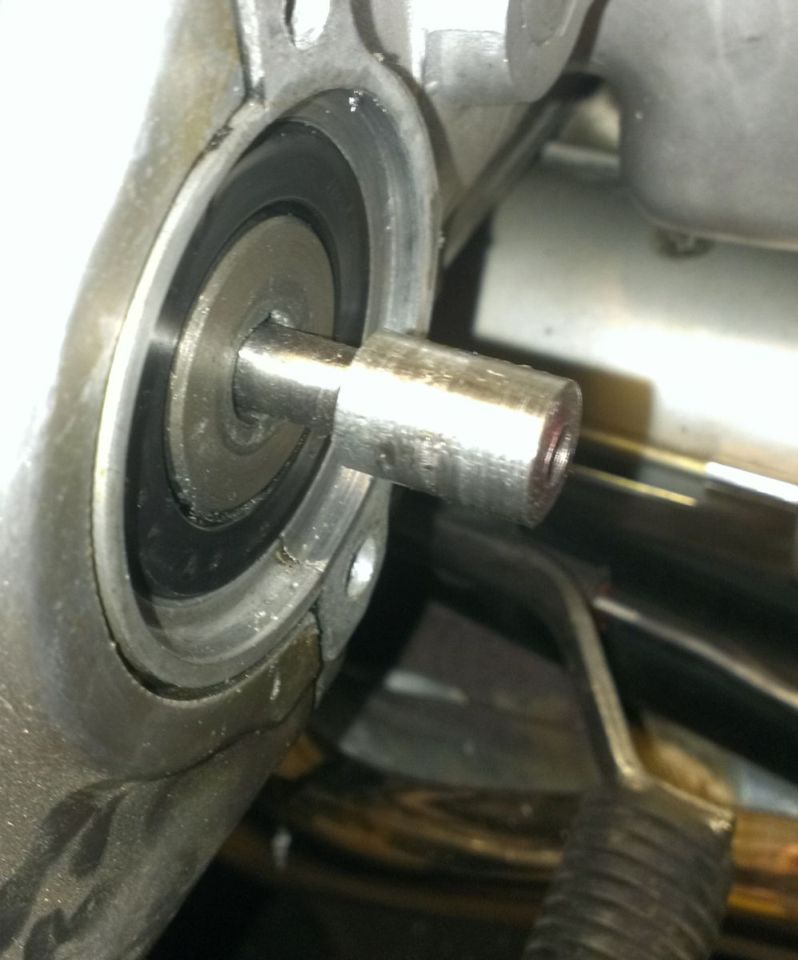
Dan,
Just so everyone knows what you and I discuss, here is a common way for us to install the encoder disc.
We manufacture a post. In this case it was designed to thread into the camshaft. There is a small aluminum "base" that has a countersunk hole.
The base is installed onto the stainless post, the encoder sits on top, and a "cap" is placed over the encoder disc (similar to an Oreo cookie).
Since the shaft is drilled and tapped for a screw, the entire assembly is sandwiched together once the timing is set.
This is for a retail customer, and is not adjustable by design, so there can be no mistakes made during installation. We could design an adjustable post for prototyping if needed.
The first picture shows the "underside" of the base where it fits snugly over the stainless steel post.
Attachments


OP
OP
- Joined
- Dec 3, 2009
- Messages
- 22,403
- Reaction score
- 238
- Location
- Van Nuys Ca.
- My Bike Models
- 1983 Interstate
2018 KLR 650
2018 BMW S1000 RR
- My Bike Logs forum link
- https://classicgoldwings.com/forums/dan-filipi.122/
That's a clever design Paul, and takes any guess work out of installing the trigger wheel, though it was very easy before.
My build in this thread is such that I have to set the wheel at a custom depth on the fly because I have adapted your 1000 housing to fit the 1200 head.
This new stud could maybe work if I adapted the module and housing depth to match it.
My build in this thread is such that I have to set the wheel at a custom depth on the fly because I have adapted your 1000 housing to fit the 1200 head.
This new stud could maybe work if I adapted the module and housing depth to match it.
OP
OP
- Joined
- Dec 3, 2009
- Messages
- 22,403
- Reaction score
- 238
- Location
- Van Nuys Ca.
- My Bike Models
- 1983 Interstate
2018 KLR 650
2018 BMW S1000 RR
- My Bike Logs forum link
- https://classicgoldwings.com/forums/dan-filipi.122/
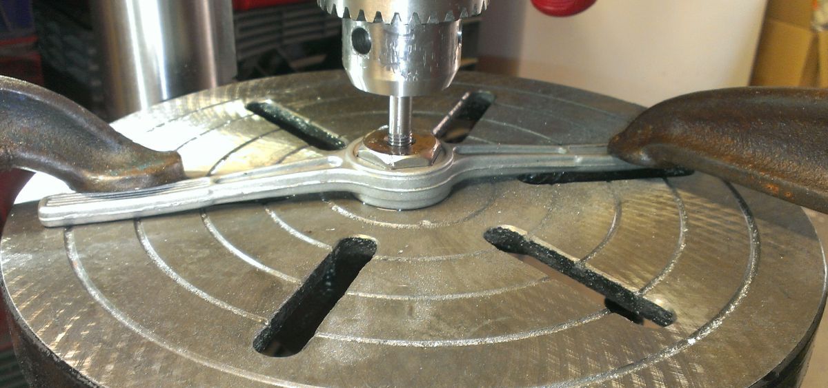
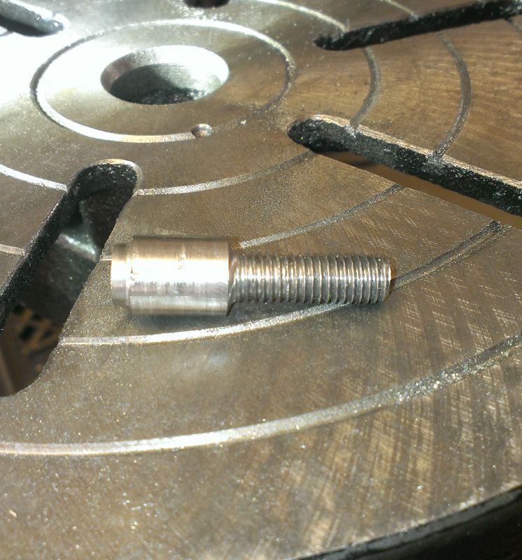
The latest:
Making a stud.
1/2" bolt, cut the head off:
Mill end down to encoder wheel diameter:
2 washers to take up some slack:
Drill and tap that end for a bolt:
Milling 1/2" bolt to 8mm for threading:
Ways to go yet:
Was going good until threading the post, when it snapped.
I know what I did wrong so the next one will be good.
Making a stud.
1/2" bolt, cut the head off:

Mill end down to encoder wheel diameter:


2 washers to take up some slack:

Drill and tap that end for a bolt:

Milling 1/2" bolt to 8mm for threading:

Ways to go yet:

Was going good until threading the post, when it snapped.

I know what I did wrong so the next one will be good.
Gotta love the new "lathe"! Cool!
OP
OP
- Joined
- Dec 3, 2009
- Messages
- 22,403
- Reaction score
- 238
- Location
- Van Nuys Ca.
- My Bike Models
- 1983 Interstate
2018 KLR 650
2018 BMW S1000 RR
- My Bike Logs forum link
- https://classicgoldwings.com/forums/dan-filipi.122/
2nd time's a charm :yahoo:
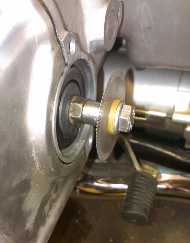
[video]https://youtu.be/jN1_at_y5NM[/video]
Tomorrow the C5 will be providing sparky's.
[video]https://youtu.be/jN1_at_y5NM[/video]
Tomorrow the C5 will be providing sparky's.
:good: :good: :good: :good: :good: thats simply great job ....five thumbs up
Very nice! Make that 6 :good: